

The increasing demand for high-bandwidth consuming applications and telecom services, are driving the exponential growth of data traffic[1]. This leads to the deployment of ultra-high data rate optical transmission systems in C-band operating at 100G to 800G and beyond and also C+L optics can be utilized in a standard single mode fiber[2]. These advances have been successful in accommodating increasing data demands but at the cost of additional optical network complexity along with the proportionally increased capital and operational costs.
On the other hand, increasing the number of standard 250µm diameter fibers in the optical fiber cable, can linearly enhance its capacity to meet the data traffic requirements. However, this leads to a larger diameter cable with significantly increased cable weight, posing challenges for deployment in the same duct space as well as straight laid deployments. Therefore, research has focused at reducing the fiber diameter from 250 µm[3] to 180 µm[4, 5] while maintaining the standard cladding diameter of 125 µm diameter. Furthermore, fiber diameter reduction can be achieved by reducing the coating diameter to 125/160 µm or the clad diameter to 80/165 µm[6, 7] . However, further fiber diameter reduction through coating diameter below 180 um, presents substantial challenges related to micro-bending and optical fiber strength.
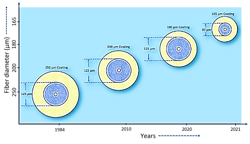
Fig.1. Cross-sectional view of the reduced coating and reduced clad diameter fibre
Therefore, fiber diameter reduction (<180 μm) research shifted towards the reduction of cladding diameter (80 μm), resulting in the 59% cross-section area reduction with respect to 125/250 µm SSMF. Figure 1 illustrates the schematic of reducing fiber diameter from 250 µm to 165 µm. This approach led to new cable designs like inter-bonded ribbon with 1728 fiber count, achieving over 26% compact cable diameter and more than 40% lighter cable weight [8] .
The use of reduced clad (RC) fiber presents a significant opportunity to make reduced diameter optical fiber cable. This advancement can greatly improve Data Centre Interconnect networks and metro-access network infrastructures by offering reduced cable diameter that are lighter and easier to install. RC fiber can help alleviate space constraints in data centers and metro-access networks. India’s first reduced-clad fiber has been developed at the STL Centre of Excellence (COE) in Aurangabad.
This blog dives into the world of RC fiber, exploring its potential benefits and the challenges it faces analyzing design factors, manufacturing considerations, and readiness for network deployment.
Benefits of Reduced Clad fiber
- Small form factor high fibre count cable
- Reduces optical fiber cable diameter, weight while maintaining similar fiber count compared to standard OF cable.
- Fiber count can be increased while maintaining same cable diameter of standard OFC.
- RC fiber cable enables longer distances blowing with fewer joint closures, resulting less link loss compared to standard OFC.
- Ease of deployments
- RC fiber enables increased fiber counts within congested duct spaces.
- Smaller micro-duct cables can be used for the same number of deployed fibers.
- Faster RC cable Installation and can be laid straight more easily.
- Miniaturization of components
- RC fiber also aimed at the small form factor (SFF) components marketplace.
- Miniaturization of components initiative save space and results in cost reduction of the components and also create new untouched applications in fiber optics markets.
- Material Efficiency
- Reduced amount of clad glass material proportionality while maintaining the same core glass region in RC fiber than standard SMF. Therefore, coating material will be also significantly reduced.
- Reduces the number of drums due to less polyethene material for drum fabrication.
- Greenfield deployments
- Reduced amount of clad glass material proportionality while maintaining the same core glass region in RC fiber than standard SMF. Therefore, coating material will be also significantly reduced.
- Reduces the number of drums due to less polyethene material for drum fabrication.
Challenges of Reduced Clad fiber
- Micro-bend loss
- Micro-bend effect refers to distortion caused by microscopic curvature, fractures, or anomalies in an optical fiber’s cladding and core.
- Contributes higher signal attenuation and results in signal power losses in the optical link.
- Occur during manufacturing as cracks and during installation due to changes in curvature.
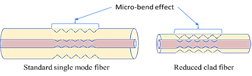
Apart from the former process, micro-bends also result from dimensional changes in fiber cabling materials, cause undesirable material interactions, resulting in signal losses in the cabling system.
2. Mechanical Challenges
- RC fiber faces mechanical challenges as of fatigue properties, and coating strip force.
- Minimum dynamic fatigue stress corrosion rest n-value should be >18 (minimum) in SSMF but will rise for 165 µm, 135 µm, and 80 µm fiber.
- Strip force test cannot be easily performed due to a quick redesign of the tool required for the test and cutting the coatings is not effective due to small cladding diameter.