The fiber optic communication industry has revolutionized the entire Telecommunication industry by providing higher performance, more reliable telecommunication links with ever-decreasing bandwidth costs. Owing to its high bandwidth capabilities and minimal attenuation or lost power, the development of optical fibers is necessary due to the innovative technologies requiring the transmission of data over thousands of kilometres with great speed, reliability, and security. The majority of optical networks have been built with a protection mechanism that may interact with the fiber separator by diverting data to a backup fiber channel in less than 50ms, to be compatible with the highest reliability standards.
However, a major problem for fiber optic communication is the faults that arise over time. It is imperative to localize its defects and diagnose them immediately because their corruption results in service interruption and a considerable loss of data and may have significant social consequences. It is also possible to record connection loss due to faulty cable installation, non-low cables, and signal lag as a fault. Consequently, an efficient oversight system is required to find the issue, pinpoint it, and minimize service disruption.
One of the most popular fiber optic testing tools is the OTDR (Optical Time Domain Reflectometer), although it is not the only one. In this article, we shall highlight some of the latest robotics technology employed in fiber anomaly detection.
Contents
- 1 Fiber fault detection
- 2 Fiber-to-the-X (FTTx) network-based OAN utilizing optical reflectors
- 3 Monitoring of optical fiber anomalies using machine learning
- 4 Fiber optic sensors
- 5 Arduino
- 6 Tactile sensing
- 7 A machine vision-based method for optical fiber preform defect detection
- 8 Fiber performance monitoring tool (FPMT)
- 9 Conclusion
- 10 FAQs
Fiber fault detection
High-speed Internet requires secure and dependable data communication in optical networks. Therefore, a critical component of delivering a stable and dependable network is defect identification and localization.
The most common fault that affects optical fibers is fiber cut, a phenomenon that occurs while work is being done on how the optical fiber cable was deployed, disrupting active fiber optic that transport traffic. Due to significant attenuation, fiber optics may also encounter another flaw. A significant advantage of fiber optics over metal wires is their low attenuation.
Because of this, any increase in their value seriously disrupts fiber optics and results in service interruptions. When fiber optic transmission is used, dispersion also causes the information stream to be distorted. The light impulses dispersed after entering the fiber; this phenomenon is known as “pulse dispersion”. The maximum number of pulses that may be broadcast and resolved at the receiver determines the system’s capacity based on the dispersion level.
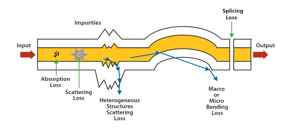
Image Credit : fiber-optic-equipment.com – Fiber optic loss
Let’s have a look at the latest tools for fiber optic used in fault detection and localization in optical fiber communication lines.
Fiber-to-the-X (FTTx) network-based OAN utilizing optical reflectors
Due to the passive nature of the network components involved, fault detection and localization in optical fiber communication lines are crucial in the optical access network (OAN). A significant amount of network data can be lost due to any link breakdown. However, the dependability and cost consequences of the devices severely restrict the application of fault detection and localization fiber optic tools.
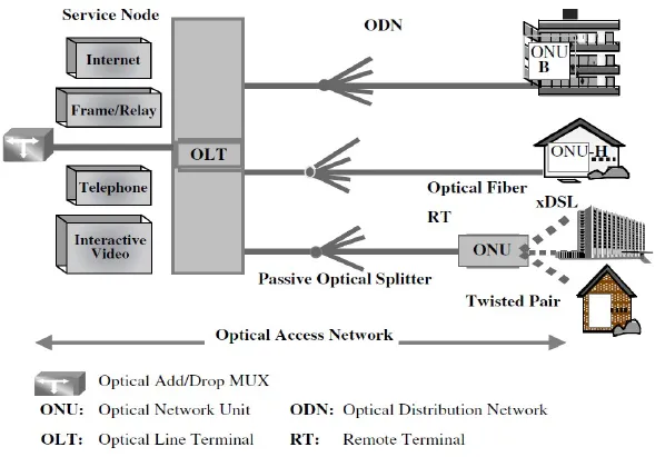
Image Credit : i.imgur.com – Optical access network
Using optical reflectors is a low-cost method of fault localization and detection in the OAN based on Fiber-to-the-x (FTTx) network. The network monitors’ reflected signals are used to find and pinpoint the defective optical link. The approaches’ ability to locate and detect network faults while they are in service at a distance of 20 kilometers is demonstrated by the experimental results.
Monitoring of optical fiber anomalies using machine learning
A data-driven method for correctly and promptly identifying, diagnosing, and localizing anomalies in the fiber network, such as fiber cuts and optical eavesdropping assaults, is one of the latest tools for fiber optic anomaly detection. This technique combines an attention-based bidirectional gated recurrent unit algorithm with an autoencoder-based anomaly detection algorithm.
Once an anomaly is recognized by the autoencoder, the attention-based bidirectional gated recurrent unit algorithm is employed for fault diagnosis and localization. With an F1 score of 96.86%, the autoencoder can identify any fiber problem or anomaly. Additionally, the attention-based bidirectional gated recurrent unit algorithm localizes the defects with an average root mean square error of 0.19 m and identifies the identified anomalies with an average accuracy of 98.2%.
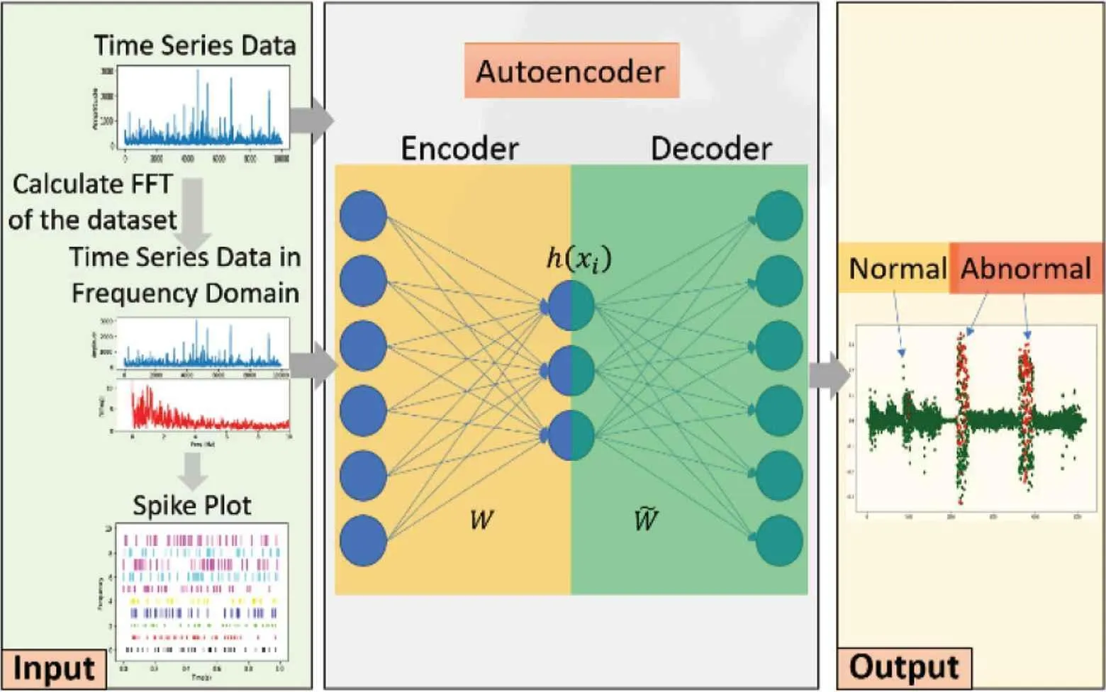
Image Credit : atlantis-press.com – Autoencoder with spiking in frequency domain for anomaly detection
Fiber optic sensors
Engineers and scientists can now undertake investigations that were previously impractical or, in some circumstances, impossible with traditional electrical sensors by employing fiber optic tools like fiber optic sensors in their research.
Thus, optical sensors are now more useful and in demand in various military, industrial, and social domains thanks to fiber optic sensors (FOSs). Compared to traditional electrical and electronic sensors, FOSs demonstrate reliable and rigid sensing activities due to their inherent advantages of lightweight, compact size, passive, low attenuation, immunity to electromagnetic interference (EMI), wide bandwidth, and environmental durability.
Image Credit : 3c1703fe8d.site.internapcdn.net – High-Speed optical sensor for detecting fiber anomalies
Arduino
In optical fiber communication, an intelligent failure detection system using Arduino is used. This fault-inspecting module aims to keep an eye on the optical fiber’s received power supply. The sensor unit is used in conjunction with the Arduino UNO, which has an Atmega 328 microcontroller, for this purpose. Proteus ISIS simulators are used to create and simulate the sensor’s output while keeping an eye on the optical fiber’s received power supply. An LDR and an opamp make up the sensor unit used in the simulation.
The fault message is shown on the LCD that is interfaced with Arduino at the same time that the date and time of the fault’s occurrence are sent to the web server if there are any abrupt changes in the optical line’s power.
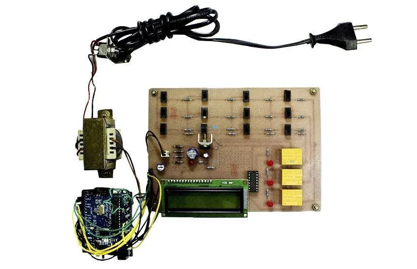
Image Credit : i.pinimg.com – Underground cable fault detection using Arduino
Tactile sensing
As Tactile Sensing offers information that remote sensors like cameras or lidars cannot, it is a useful technique for manipulating robots. In unstructured situations, where the robot’s internal image of the manipulated objects is hazy, touch is very important.
A soft sensor built onto the tip of a robotic hand’s finger transmits tactile feedback. The sensor comprises an optical fiber with Fiber Bragg Gratings (FBGs) transducers inserted inside it that is attached to a hard hand with a soft polymeric material. The system’s capacity to gather information is evaluated by a series of tasks involving the grasp of various items under varied circumstances.
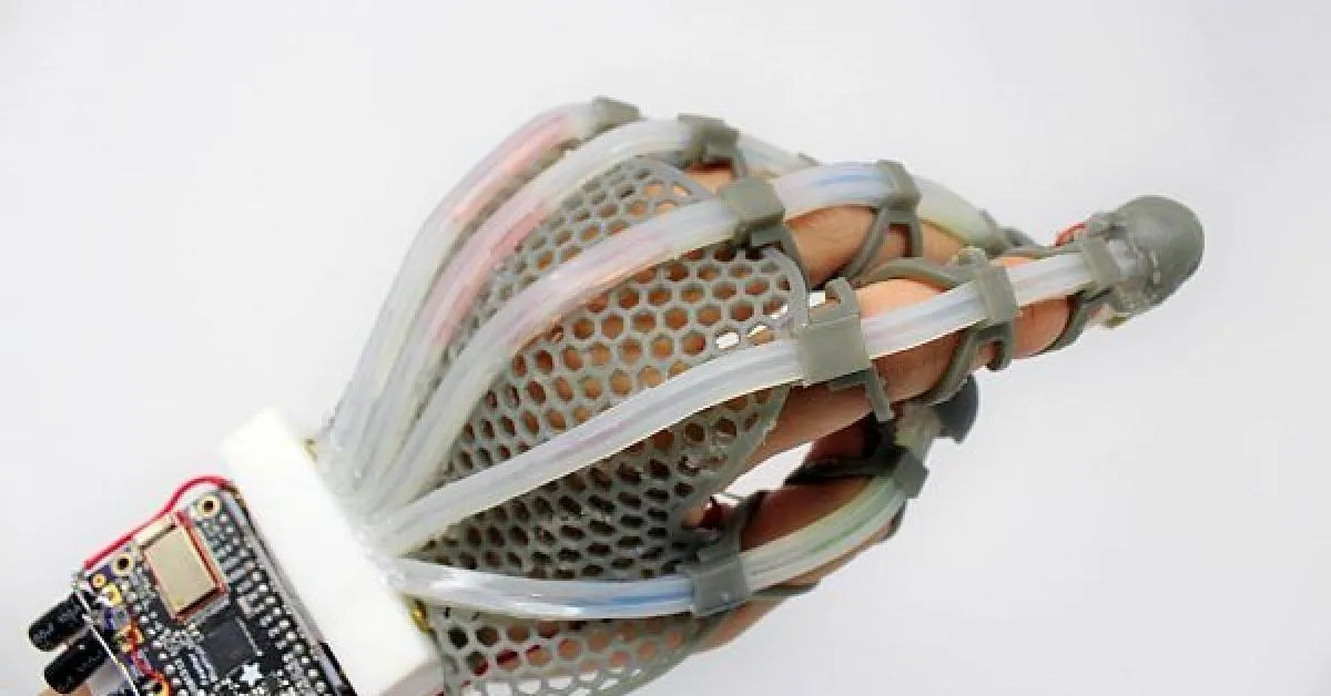
Image Credit : eenews.cdnartwhere.eu – Fiber optic sensors
According to the results, a classifier based on the robotic hand’s sensor outputs can detect the size and rigidity of the operated items with 99.36 and 100% accuracy, respectively. The outputs of these sensor-based fiber optic tools also demonstrate the capacity to do dynamic manipulation tasks, which require the alteration of finger position dependent on the condition of the gripped objects and to grasp delicate objects without breakage or slippage.
A machine vision-based method for optical fiber preform defect detection
For defect identification, most domestic producers employ human eye examination compared to fiber optic testing tools. Manual inspection is sluggish and subjective, and it is very simple for problems like missed inspections and false inspections to occur, which significantly impacts the quality of the products.
A machine vision-based flaw detection method is used for optical fiber preforms to get the full-angle image of the optical fiber preform first by using the experimental platform for defect identification on the optical fiber preform.
The full-angle image is then preprocessed after the proposed technique determines the boundary of the optical fiber preform in the image. Additionally, the full-angle image is used to track the flaws, and the tracking data is saved. Finally, tracking data determines the defect’s location, size, and type. Experiments have proven that this technique can detect flaws in optical fiber preforms.
Fiber performance monitoring tool (FPMT)
The goal of these fiber optic testing tools is to increase the availability and reliability of optical networks by remotely identifying and estimating fiber problems without interrupting data flow. The new proposed Fiber Performance Monitoring Technique (FPMT) uses an optical time domain reflectometer to detect various fiber failures, such as fiber breaks, end-face contamination, end-face burning, high insertion losses in connectors and interconnections, or mismatches between fiber cable types. This is a departure from the traditional method.
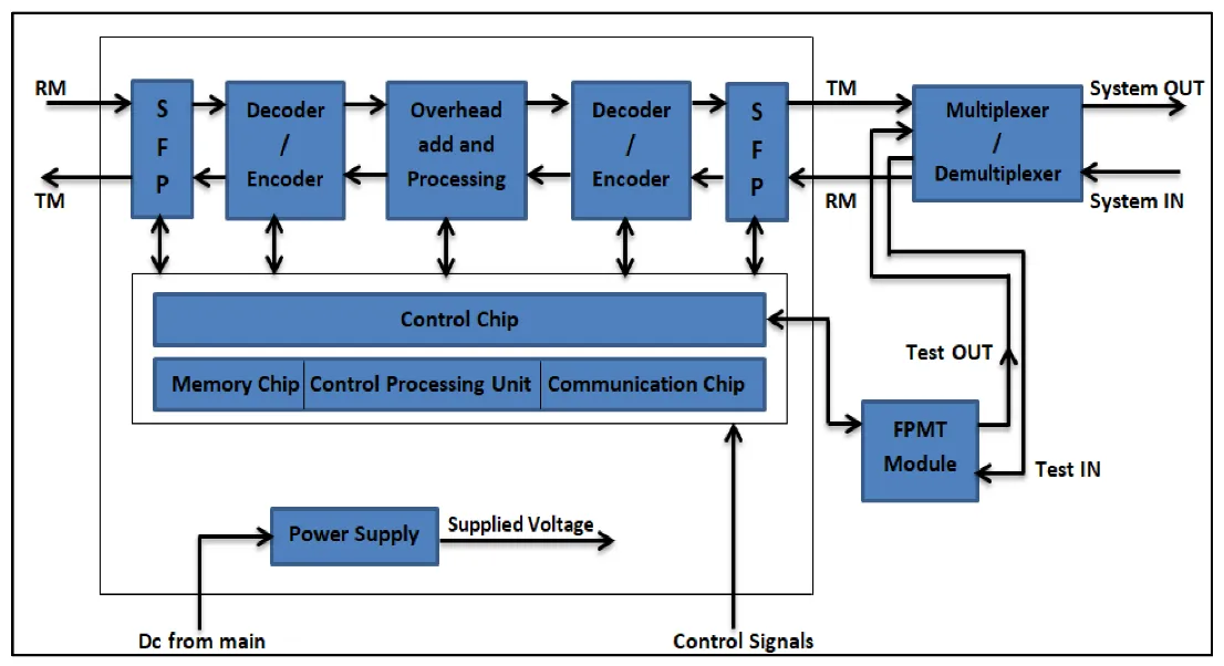
Image Credit : mdpi.com – Fiber Performance Monitoring Tool
The methodology used to detect fiber failures in the network is based on analyzing the feedback of the reflected signal and the pattern shape of the reflection. This allows for a broader range of distance testing and performance monitoring. This can be used inside an optical network in real-time and remotely by integrating with an OSC board. This method can enhance the system power budget with a negligible insertion loss of 0.4 dB and can detect fiber problems with an average measurement accuracy of up to 99.8% over a distance of up to 150 km.
Multiple fiber failure types, including fiber breaks, end-face contamination, end-face burning, and significant insertion losses on the connector and junction between two separate fiber cables, were found by FPMT. The method showed better performance in the following areas: reducing insertion loss while increasing the system power budget, providing a wider range of distance testing and performance monitoring, high measurement accuracy, low deviation value, and numerous types of fiber faults detected.
Conclusion
Optical fibers, the data transmission channel that connects billions of users worldwide, are susceptible to a wide range of anomalies brought on by physical attacks with malicious intent [such as optical eavesdropping (fiber tapping)] and hard failures. Such abnormalities may interrupt networks, resulting in significant financial and data losses, jeopardizing optical networks’ secrecy by allowing unwanted access to the data transmitted, or gradually impairing network performance. Therefore, effective anomaly detection, diagnosis, and localization systems with effective fiber optic tools must be put into practice to improve the availability and reliability of optical networks.
FAQs
1. What is Fiber Attenuation?
A telecommunications term for a decrease in signal intensity is Attenuation. This may happen while sending signals over great distances. Decibels (dB) can be used to compute it in terms of voltage.
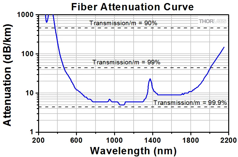
Image Credit : thorlabs.com – Fiber Attenuation
A fiber’s attenuation, which is related to wavelength, is the decrease in optical power between two cross-sections of a fiber. Attenuations come in various forms, including intentional, automatic, and environmental. Scattering, absorption, and optical losses resulting from connections and splices are the main causes of attenuation. When the attenuation of the signal is really high, it becomes incoherent. Therefore, the majority of networks employ repeaters to boost signal strength on a regular basis.
2. What various types of dispersion are there in optical fibers?
Dispersion of Materials: Also known as color dispersion. This results from the refractive index’s wavelength relationship.
Wavelength Dispersion: In fibers, the energy distortion for the fundamental mode is wavelength dependent. This primarily affects single mode. The energy mode spreads through the sheathing as the wavelength gets longer.
Polarization Mode Dispersion: This results from the lack of perfectly symmetric fibers, which results in varying velocities for each polarization mode.
3. What are the most typical reasons why fiber optic systems fail?
Following are some of the most typical fiber optic cable issues and some potential solutions:
- Broken fibers from physical strain or excessive bending;
- Insufficient transmitting power;
- Excessive signal loss due to a cable span that is too long;
- Excessive signal loss because of a contaminated connector;
- Excessive signal loss because of too many splices or connectors;
- Improper connection of fiber to the patch panel or in the splice tray;
- Excessive signal loss due to faulty splices or connectors is an example of signal loss.
Usually, a broken cable is the cause of a connection that is completely dead. However, there are a number of reasons why the connection could be sporadic:
- Too many or poor-quality splices in the cable may cause it to attenuate too much.
- Connectors can become contaminated by things like dust, fingerprints, scrapes, and humidity.
- There are poor connections in the wiring closet;
- The transmitter signal is weak.
4. What is OTDR?
An Optical Time Domain Reflectometer (OTDR) is a widely used tool for identifying defects in fiber optic networks. It is used in the construction, certification, maintenance, and troubleshooting of fiber optic networks and checks the fiber cable’s integrity. An OTDR can show the cable mapping, evaluate termination quality, and locate defects affecting network performance. It enables the identification of problems throughout a channel’s length that could influence long-term dependability. Segment length, the location and insertion loss of connections and splices, and other occurrences like severe bends that may have occurred during or after cable installation are all characteristics that OTDRs may identify. Newer technologies also have restrictions on reflectance for each connector in the link, which can only be validated using 100BASE-DR.